2022 CQWW CW Contest! New tower on air! Old A3S and Yaesu rotor back in the saddle!

Today was the 2022 CQWW CW contest, and while I haven’t normally posted about operating activities, I decided that it would good to document some of them (before I forget, which is something that happens more as we age, as we all know — or at least as we know till we forget).

This weekend was really the coming out party for my new tower, the US Tower model TX -455, and a homecoming for the Cushcraft A3S tribander (which you can see on top of this tower in the picture above). Also pictured at the top of the tower is the Cushcraft tribander for 2m/70cm (the easy-to-remember model #A270-10S!). The tower was installed end of September, but needed 30 days to cure properly, then had to be inspected, and a couple weeks ago I was ready to install the A3S but discovered I was missing the mast-to-boom plate, so I had to make a quick order to MFJ/Cushcraft to get a quick replacement (thank goodness they still make it, and they were quick to send at reasonable cost).

I had done some limited operating with the A3S in the past week. I worked a Japanese ham on 15m who said he thought I was a west coast station, and was surprised I was only running 100W! I thanked him for the nice complement, and it excited me for the future with this antenna and for the CQWW contest.

The A3S, the VHF/UHF antenna and the rotor all have some nostalgia for me. I was forced to abandon my previous crank-up tower back in about 2004, a similarly sized 45′ crank-up US tower in Tucson. This was due to many “life changes” that took place at that time. I always sort of kept the torch lit for the chance to set up a tower and my antennas again, and through many moves around the country and a career change, I somehow managed to keep these parts together. Now almost 20 years later, to see them working (and working very well!) after such a long downtime is amazing and gratifying. Now I need to make up for some lost time!

I do plan to replace the A3S with a Mosley antenna (with another crazy model number I’m too lazy to look up) that will give me not only 20/15/10 but also 17/12/6. This will allow me to use a single coax for the entire shebang, and give me 3 elements on all of those bands. I couldn’t pass that up! As with many things these days however, there is a significant lag time in delivery, and I won’t see this antenna until January. So, the A3S rides again, for now.

CQWW CW

I missed the CQWW SSB contest because the concrete base was still curing. But I enjoy CW and was anxious to give it a go.

I fired up the good old N1MM contesting software and the Kenwood TS-2000 (also a rig from 20 years ago!) and coupled it to a new Vibroplex iambic paddle (I wanted to change things up a bit from my ~30 year old Bencher) and away I went. A few months ago for fun I got a “Geocron” module and purchased a big TV monitor to display the world map up above the operating desk of the shack. I turned that on so that I could keep track of grayline prop (as well as, for kicks, see the tracks of all the ham sats and some weather patterns). There are free web-based world maps that also show the sun track of course, but this seemed like a cool gadget and I guess I fell prey to some HRO salesmanship as well!

The operating position at WF7I near Natural Bridge, VA

I taped last year’s score — about 30,000 points — onto a trash can facing me as I operated! This gave me some added incentive. I didn’t realize I would do almost 10 times better this year! Phenomenal.

As I say I’m not “A Contester” as such but I do enjoy one or two each year. I’ve grown to enjoy CQWW. I have found that at sunspot minimum and with compromised antennas, it can be an exercise in frustration yelling into a microphone or calling DX stations endlessly with no reply. But with a decent station, it can be a blast. And that’s what I experienced this round.

I started out Friday night at 7 PM EST, right when the contest began. It runs for 48 hours but I rarely spend more than maybe 10 hours total for both days, due to interest, frustration, or just other things I have going on for the weekend. I’m sure I spent more than the usual 10 hours this time though.

I’m sure avid contestors have a game plan laid out in terms of what band at what time. I had a basic idea of what I wanted to accomplish. I decided to start at 20m, knowing that likely 10 and 15 would be mostly dead by then. As it turned out, 20m was also on its way out, but I did make quite a few QSOs there. I then decided I would move down as the night went on. The idea was to end up on 160m around midnight, spend an hour or two there and then go to bed by 1-2 AM.

What ended up happening was a bit different. 40m was HOPPING. I’ve been a ham since 1985, and I’m sure there have been times, maybe on Field Days or one or two other contests like sweepstakes, etc, where the bands have been almost as crowded. But honestly, I just can’t recall a band being THIS DENSE with stations, especially DX. It took all of my skill with the DSP filters on the TS-2000 to carefully navigate between stations. And I ended up spending about 4 hours on that band, just to work from bottom to top! I didn’t even try to hold a frequency, it was all search and pounce (which is really the main way I ever work contests anyway).

So I piled up something like 60 contacts over that span, which although that’s a small number by serious contester standards, that is a TON for me, especially with search and pounce and careful tuning to make sure I was spot on the sender’s frequency (everyone had such narrow band filters on, they would never hear me otherwise). The code speed was also insane, as was pointed out by a local ham club member who I spoke to this evening. Everyone seems to be using keyboard CW and 30-40 WPM, which is very hard to copy by ear unless you are really great at high speed CW. The characters of S, 5 and H can sound alike, and knowing a D from a B (or a 1) can be a challenge, especially coupled with lack of sleep in day 2! My guess is most of the hams are also using software CW decoders although it’s hard to say for sure, as many of those are not great at perfect copy.

I got down to 80m and worked about 30 more before moving down to 160m around 1 AM! I was too tired to do much and honestly “top band” was not in top shape for me. My 160m antenna works pretty great, it’s a full-wave loop at 30 ft. Sure, it would probably perform a lot better at 100 ft, but I was doing great to get it as high as it is on multiple telescoping Rohn masts, so for now I can’t complain about it. I seem to generally hear everything everyone else does, and most of the rag chewers on the band blow my S-meter to 20 or 30 over. I mean, it’s 500 feet of wire after all.

Something I noticed this year which seems different from last year was a sense of improved loop performance. Stations heard me much better on 40m, and stations I could literally barely hear on 80m would call me back first try. This seems new, and the only major change since last year was the installation of 5x60ft buried 6-gauge copper ground wire for the tower’s grounding system. I did run a lead over to the loop antennas ground connection at the feed point. I wonder if some slight improvement in ground conductivity has helped. Other than that, it would have to just be chalked up to propagation. Solar flux was just over 100, which I believe was better than last year’s, but was still not as high as past months of this year sadly.

I decided after a few less than amazing QSOs on 160 I would pack it in at 2 AM. I was able to get up late Saturday morning and jump on 20m for a few QSOs (not many) before spending the day on 10 and 15. Those bands were certainly doing much better than when using the loop last year, but not THAT much better. I guess I really expected a tsunami of signals and what I got was just a little more than before. I attribute that to solar conditions mainly. That night I decided I would focus more on 20m and then 80 and 160 and “gloss over” 40. However, the night had other ideas, and 40m was once again crazy good with stations all around the globe it seemed calling me and densely packed on the dial. So I decided I wouldn’t do much on 80 and 160 and instead pack things up early (10 PM) and get up at 5 AM Sunday and see what I could do on the low bands at that time.

Around 6 AM Sunday I was able to grab a ZL station on 80m. It was a great accomplishment because there was a pileup of stations that, one could easily surmise, were running higher power than I, and probably better antennas. I somehow persevered and found an opening, and snagged him! It was a tough slog for me with 100W, and I had to repeat my call and report many times. The op was incredibly patient (ZM1A, “Jacky”), and in fact I sent him a thank-you email afterward. Down on 160m I had another catch, not quite as great perhaps, of a cuban station. That was memorable because the venerable K1ZZ himself was in a small pileup of stations attempting to work him. At one point, the op paused for a few minutes. When he returned, I was quick to get in my call, and nabbed him before the pileup re-formed!

In general there was a lot more joy on Sunday for the higher bands. When I went to bed Saturday night, my vision was to aim my beam at Europe and work 20 like mad and rack up the points. My goal was to at least break through 100,000 points for the weekend effort. I felt that with my beam at 60 ft, unless the band really collapsed I ought to be able to get some good results. And as it happened, I was absolutely correct! 20 was bonkers, if possible it was even more dense than 40 had been. I had stations literally right on top of one another from the same DX entities (likely they couldn’t hear one another). It took all the skill I had with my rig to dial things in and squeeze between stations. The QSO rates were intense even with search and pounce. Literally every kHz was crammed with 1-2 ops. It felt almost like FT8!

I did get a few new DXCC entities from this weekend of course, and I should finally have my DXCC award now (I never collected cards back in the day, and again I just never did enough contesting or chased it hard enough to collect the award). Now with LOTW, it is fun and easy to collect the credits and I hope to be able to hang the certificate on my wall (along with the WAS) very soon! One of the more memorable contacts was a station in Iceland, who I caught just when he turned on his radio apparently, and got his rare zone. I also worked a small island off the coast of Madagascar, and I worked several Ukranian stations. Japan flooded in on 20m shortly after dark on Saturday night, as expected, and I was again impressed with their operating skill and politeness. And I’m always eternally grateful for these amazing club stations and massively built professional DX stations that can hear a pin drop on Jupiter, and so can easily pull my signal out of the noise and give me the ubiquitous “5NN”.

Concluding thoughts

Contesting can be a lot of fun and CQWW has become one of my favorites. This year, having the debut of a new tower, having the old friend A3S back at my side as well as the trusty TS-2000, and some decent solar conditions made it a real joy to work. I look forward to a few more improvements with radio (a TS-990s upcoming) as well as the Mosely yagi in coming months, and I expect to do a few more contests each year as a regular activity.

Posted in Uncategorized | Leave a comment

Tri-band NE-602/LM-386 based rig with digital display!

My first tribander of my own!!

Introduction and background

Before I begin, a quick trip in the “way back” machine is in order.

Picture early 1980s, somewhere around 1982. 10 years old, not yet a ham and just starting with shortwave. My only radio was a Realistic DX-100. It was a chore to tune but it brought in another world. Before the internet, receiving signals directly from the other side of the world was like magic. People you would tell would be amazed.

This drifty analog radio cost $100 at the time, which in today’s dollars would be around $300. It was not a great radio even in those days, but it was very expensive for a kid. I treasured it. I strung up a long wire across my parent’s backyard and ran a cable in through my window. I even had a grounding established to metal water pipes.

This radio not only drifted badly (you had to keep your fingers on the tuning knob; after 5-10 minutes the station would drift completely away) but it was VERY hard to tune on SSB. The BFO (on a good day) was pretty touchy, and the drift affected SSB even worse than AM. And on top of all that, strong signals from the longwire would overload the radio on SSB, making signals completely unintelligible. At the time, I didn’t know what “overload” was, and was learning about SSB. I was just happy to receive all these foreign broadcasts (which, in those days, were still plentiful on the bands).

A few years passed and I got my ham ticket and upgraded my radios. My first was an old tube-type Galaxy III. Not too drifty, but still analog. I dreamed of a radio with an accurate digital display, but those were very very expensive in those days. I finally obtained a used Kenwood TS-530 S, sometime in the late 1980s, and I was over the moon. Finally — stability, digital readout, sensitivity. A true joy to be on the air with.

As years rolled by I gradually developed an interest in circuits and building. I did not start out with this interest, however. It has gradually built in me over time. Somewhere around 2000 I began in earnest to look into “QRP” and building my own radios, and this is where I came across “Experimental Methods in RF Design” and the NE-602/LM-386 based radios.

The original circuit from Experimental Methods in RF Design

As I began to try to build this thing, I soon ran into many obstacles. Even though it seemed like a simple circuit, the oscillator on-chip would not oscillate at all. Furthermore, I could not get ANY oscillator to oscillate, even ones I built myself (based on the Colpitts design)! I do not recollect now what the issues were with my own oscillators, but I ended up designing a Hartley oscillator instead, and incorporating that into this circuit instead. That worked! I was thrilled! The circuit did not work great, I remember it being hammered by out-of-band signals. I think I had trouble obtaining some of the component values for the caps, as my junk box was not that great at the time (I was only really starting as a builder). This was before the internet had quite taken off as a place to rapidly order everything under the sun, so I was still going to Radio Shack and making do as best as I could. Also there wasn’t always a “Google-able” answer to every question in my mind! Sometimes I ran aground and it took weeks to figure it out.

At that stage I had my bachelors and masters in electrical engineering (“EE”) and was working in the cell phone industry. However, I soon learned with this (and related) radio projects that there were a lot of things I either didn’t learn about in school, or that were only dealt with at a very high-level theoretical/mathematical basis. I found myself going to discussion forums with other hams; a thing called “Elmer 101” was very useful in understanding a related circuit for the Small Wonder Labs kits; and I remember a lot of frustrations in learning proper practical techniques for construction.

Fast forward to more recent times. In about 2013 I re-built this same circuit, after having had more education (graduate-level work in EE that actually encompassed RF design). Basically what that background got me was the mod to put in some bandpass filtering, to attempt a transformer at the front end to better match impedances, and to put it into a tidy box with a fine tuner and a main tuner. It was a 40 m rig, and there is also a blog entry for it here somewhere (I called it the “MRAD 40”, not sure now what that stands for!).

In the intervening years, I’d build the SW-20, SW-40 and the Rockmite 40 from Small Wonder Labs (all NE-602 rigs) as well as Ashar Farhan’s Bitx-20A SSB rig (from a kit by Hendricks). Being kits, I never really ran into serious obstacles that stopped me, as I had with that old circuit from 2000. They more or less came together and I stuff their boards. I tried my best to build them in stages, test and model them, and blog them here. I wanted to learn as much as I could. And I DID learn a lot from those. But, something was missing. I felt like for the past 20 years that I’d been sporadically building (because there were many gaps of inactivity as well…), I really was staying “within the lines” more or less. Also the complexity of some of these radios I felt made it a bit harder to master the basics. Because of my engineering background, I guess I always felt compelled to jump to the head of the line, that going “basic” was absurd for me and I should be working on bigger and better designs, etc. However, I realized after awhile that I had gaps in my understanding of some of the fundamentals of design and construction of radios. I yearned for the radio of yore, that simplistic yet fascinating basic diagram from Experimental Methods! I missed the days of scrounging to build various types of oscillators, playing with component values, scratching my head when something didn’t work.

In essence, I wanted to go back to “off road”. I was tired of staying within the lines. I was never going to truly learn that way.

So, here we are: 2019-2020. And the tri-bander with a digital display!

When thinking of what to work on, I not only wanted to go back to my roots with the NE-602 but I also wanted to put a digital display on it. I figured that in 2019 surely there were some cheap options for this, pre-made (I would still like to learn how to homebrew these as well — this is a work in progress with the Arduino, and subject for future blog posts!). Sure enough, I discovered the “QRP Guys” digital frequency counter! This would be my foundation for this radio. But I also didn’t want to just re-create what I’d already done with the MRAD-40. I wanted to make more bands, at least 3 if not 4. This would fulfill a dream of my youth as well as dreams of my middle-age: have a radio, that is stable and sensitive with a digital display; and, design it myself!

Thus, this radio was born!

General description

I’ve recorded a great little YouTube video of this circuit, and I would direct anyone who wants to really see how things are connected together and how they work to view that. Below are  snapshots from LT Spice showing the schematic.

Tri-band schematic showing antenna and BPFs, transformer, NE602, LM386, main and fine tuner, voltage regulator and the 40 m oscillator.

The 40 and 80 m VFOs.

Some enhancements:

— Three bands, with three separate VFOs
— Digital display/frequency counter, as mentioned
— Using voltage regulator as opposed to Zener diode
— Using “Manhattan style” construction instead of perfboard; sockets on all chips; groundplane easy to access; toroids mounted on drywall anchor standoffs instead of haphazard methods
— Careful adjustment of both signal input to NE-602 from transformer as well as signal level of LO into NE-602, to reduce/avoid spurious out-of-band signal generation effects
— Shielded cable (RG-316) for runs between elements of VFO and mixer to reduce noise/spurious effects

A view inside! Pardon some red paint spray on some areas. A 3-position, 4 pole rotary switch is at upper-left. The three VFO oscillators are at the right end of the board, from top to bottom (Colpitts with 3904 transistors). Digital display board at center-left. Main tuner air variable cap at bottom left; fine tuner (obscured by switch) at upper-left. RF gain pot at center-right. RF input SO-239 at upper-right. Power comes in via an M-type connector, bottom right. All components glued on with super glue and using Manhattan-style pads (portions of circuit board cut out into pads), made by QRP Me.

Rear view. 5k audio taper pot for RF gain. Type M connector for power (I use a Bioenno Power 12V pack for this and several other kit rigs, with SOTA!).

Front view, using external amplified speakers (provides a much-needed volume capability!).

As with the original circuit, this is a direct-conversion style radio, meaning that RF is converted down to audio frequencies and there is no IF. With the NE-602 mixer, you’re getting both sidebands as output. So, bands seem extra crowded! As explained in the video, I incorporated band pass filters to help with overloading and selectivity. These are simple series resonant circuits, and I used the inexpensive (and now ubiquitous) NanoVNA to help optimize these (along with an Excel spreadsheet). The VFOs were painstakingly designed and re-designed to obtain the proper overall tuning range and for stability. Using NP0 ceramic capacitors are a must here; garden variety ceramics can add terrible drift (both up AND down in frequency!). My video talks about this as well. I opted to use a voltage regulator chip instead of a zener, given some difficulties with the zener option (higher current draw than I wanted and some blown zeners!) and having a plentiful supply of these regulators in my supply cabinet.

Construction was Manhattan style and I made use of many pads produced by QRP Me years ago (and it looks like he still makes them).  These pads and also some drywall anchors were glued to the copper clad circuit board. Those anchors I found were great for supporting the toroids; different sizes can be used for different sized toroids.

I struggled mightily with a few aspects of this radio. Here are the top three, broken down into bullet points. I may wish to study these in more depth soon to find out answers:

  • First, when trying to match the 50 ohm antenna input to the ~1500 ohm input of the NE-602, I kept finding it impossible to build a simple transformer that actually worked across all three bands! You need a turns ratio of about 5.5 for this, and for some reason no matter what cores I used and what ratios of windings, I could not obtain this high of a ratio for the 20 m band (40 and 80 were not a problem). This is a subject for more investigation. In the end, I settled on the design shown in the schematic. It is not a perfect match. However, signals are LOUD into this rig, it is quite sensitive, and most of the time I find myself reducing RF gain, so a “better” match may not be all that helpful anyway.
  • Another weird aspect, and I feel this is something I probably should know, but maybe I’m not smart enough! I tried to wind that same antenna transformer originally as a balun. So, the signal with respect to ground heading into the NE-602, at each end of the coil, was equal and opposite in sign (ie, balanced). This did not work! In fact it basically perfectly nulled the antenna signal to zero, and the mixer had no input. Again, maybe this is something from engineering 101 — maybe I missed that class. I intend to go back and try to do some circuit analysis, maybe on paper first and then on LTSpice, to figure this out. My first thought is that a chip with balanced inputs would want a balanced signal. Instead, it seems like an unbalanced-style transformer input was what worked.
  • The third major frustration for me involved the on-board oscillator of the NE602. I was not able to reliably obtain oscillation for all three bands. Sometimes one or two would oscillate but even then the amplitudes were quite small (barely detectable on the scope) and oscillation would come and go (unreliable). This was a problem both in the 2013 edition of this radio (the “MRAD-40”) as well as the original beast I made in ~2000. Both times I had to build my own outboard oscillator to make it work. The same thing happened here.

Finally, the last bit that stymied me for weeks (admittedly, I couldn’t work on this radio for days at a time due to many other “life” things going on at the time) was an issue with out of band junk overwhelming the radio. I would turn it on, and I would hear 3-4 LOUD broadcast stations, both shortwave and even AM broadcast, dominating reception. Underneath all that there were the intended ham signals from the bands. But this of course made the radio completely unusable. In the past I would possibly abandon the project at this point, but I’ve seen this sort of thing before, and with persistence and experimentation one can eventually find a way out of it.

There was no single solution to this problem, but a combination of the following seemed to solve it. First I ran many shielded cables, basically two for each VFO section, to avoid having additional RF overwhelming the 602. Then I found that the LO injection was just too high. These Colpitts oscillators were optimized for max output, and they REALLY output well, maybe almost enough for a QRPp transmitter! But this is not needed here. I ended up putting in a 330k resistor in series with the inputs from the VFOs and that went a long way towards eliminating the worst of the overloading style effects. Running the RF gain control wide-open also often worsens this, and backing off the gain a bit helps a lot. Finally I also RF-grounded the un-used pin 7 of the 602 chip (with 0.01 uF cap) as well as running a 0.01 uF cap between pins 4 and 5 and between voltage supply rails everywhere and ground. The latter is good practice for RF design anyway. The former I have to admit to not knowing why it helped, but it seemed to, and I would need to research it more to try to find out.

Operation

I would direct interested parties to my YouTube channel and check out some of my band scan videos to see how this thing works. In general — I am pleased beyond measure! This little radio is one I can take to the bedside and run off a battery and headphones and tune around. It is sensitive, and after a 20-30 min warmup it is remarkably stable and requires essentially no touch-up on tuning (especially on 40 and 80 m; 20 m is more touchy, but I probably have less-than-optimal ceramic caps in that VFO). The radio draws 44 mA; about half of that (20 mA) is from the frequency counter display. If someone wants a very low-current consumption, one could switch out the display and have a 24 mA draw receiver! But, honestly with today’s battery tech, this thing will take forever to drain something like the Bioenno 3 Ah pack (68 hours!). To have SSB, stability, a digital display and the ease of analog tuning along with low current draw — all with a homebuilt radio that you can easily repair or upgrade yourself — is amazing. I’ve put together much more capable radios, but this one is my favorite overall and I find myself using it a lot.

The radio is still prone to overload and is especially so late at night when all the high-powered and relatively local shortwave broadcasters come online. But this is not so bad as to become an annoyance; often the signal will drift in and drift out and that’s it. Sometimes lowering RF gain a tad will eliminate it altogether.

This radio is not as sensitive as a modern Kenwood/Yaesu/Icom/Elecraft etc. But it is sensitive enough that it outperforms my old DX-100 by far, and is much easier to tune (and more stable!). It is a relatively small rig and could be put into a much smaller package that what is shown here; I like lots of room to solder and work with and am not that fond of tiny enclosures.

The biggest issues I have with this little rig have to do with the audio. I would like to install a volume control mechanism of some sort, perhaps an audio AGC or just a variable gain pot. Having an outboard S-meter would be cool and I may investigate this too. But the audio is also harsh with some distortions, and it could be worth some investment in time to make some mods on that end.

Concluding thoughts

I am contemplating taking this on SOTA along with another home-made (and very old) crystal controlled transmitter!  Stay tuned.

Posted in Uncategorized | 4 Comments

N7VE VSWR indicators for QRP

The “Easy SWR indicator” circuit from Pacific Antenna

In need of a portable VSWR “meter”

During my SOTA evolution, I discovered I was having to haul a VSWR meter with me in order to tune my “SuperAntenna” vertical. It adds considerable weight and it was far too nice of an instrument to risk damage out on the trail (see the Diamond SX-600 image below).

While one can argue that one should use an antenna that does not require tuning, and I’m sure there are arguments for and against using vertical antennas, etc, I do find this particular antenna to be very lightweight and convenient to set up in a hurry. The only inconvenience was the tuning of it — sliding a tap up and down a coil assembly.

I did mark off onto the coil (roughly) some spots for where to adjust it for the various ham bands. However, it is extremely touchy, and just a slight slip of a couple of mm can make the difference between 1:1 and 10:1 VSWR, especially on the higher bands.

I came across a really neat solution on the Pacific Antenna webpage (see top photo). They will sell this as a very inexpensive kit. I almost purchased the kit but then I realized I could easily make this circuit using parts in my shack. It is extremely simple!

Quick breadboard version

I immediately threw this circuit together and ran some tests. Sure enough, it worked quite well. The LED will extinguish as VSWR drops below about 1.5:1, which is quite adequate. You cannot really zero in on exactly 1:1 with this particular circuit. I was amazed at how well this worked and how compact this could be. It also was quite clever, and I’m drawn towards simple circuits that pack a punch.

How does this thing work?

Soon after I built this, I started to realize I wasn’t quite sure how it worked. And of course, this bothered me a lot, because it looks very simple! After hours on the bench and scope, and more hours on LTSpice, I feel like I mostly know how it works! But I could still be missing some finer points.

To analyze this, I place a source signal first on the left side (transmitter side) and then on the right (load) side. I discovered that, regardless of (reasonable) signal level applied to the left side, the LED will not light.

With a signal source applied to the left, with some analysis, it can be seen that the voltage on either side of diode D2 is virtually identical. The difference is not enough to turn on D2, so that is essentially an open circuit. And the vast majority of voltage is dropped across R4. What is left at the top of C2 is never high enough to turn on the LED. So, forward power will have no effect on lighting the LED (at least at typical QRP levels, and I don’t go over 2 W).

What should also be noted is that the equivalent resistance of the circuit looking to the right from the source side (and into a 50 ohm transmission line and load) is 50 ohms (100 ohms in parallel with 100 ohms). Therefore, the circuit itself will not cause a reflected wave back towards the transmitter, which is good! We want the RF to transmit through to the load, and only pick up THOSE reflections with our little circuit.

Now, to look at the circuit with a source applied to the left side of the circuit. This is where it gets more confusing to a degree.

At first glance, it appears that most of the voltage will again drop across R4 and what is left will be drained to ground by C2. There is not enough voltage to power the LED.  This is roughly true for the first AC cycle. But things change after that. See snapshot from LTSpice below (source voltage 10V, 1 MHz).

As you can see, with each successive cycle the voltages build until eventually we reach the turn-on voltage of the LED of around 700 mV. Why is this happening?

One huge difference is that D2 is no longer always cut off. During positive parts of the cycle, it is cut off. But when the supply goes negative, it turns on. Now current flows up from ground through C2 and then R4; through C1, the current is at a much higher magnitude than during the positive cycle due to the D2 contribution (LTSpice shows it is about 4 times higher). This asymmetry has the effect of gradually establishing biases on C2 and C1. On LTSpice you can see this by virtue of the fact that the node below C1 and above R4 develops a peak voltage (during positive supply swing) that is actually HIGHER than the supply voltage (in this case, 16 V instead of 10 V).

The current flood during that negative half cycle of the supply voltage, through D2 that charges C1, has little effect on the voltage across C2. However, C2 DOES develop a charge. On the POSITIVE half-cycle of the supply waveform, C2 benefits from the higher voltage at the node above R4. Because the waveform on that node is shifted to the positive — positive voltage peaks at 16 V and negative dips to only -3.7 V — the large favoritism for the positive voltages ends up gradually biasing C2 in such a way that eventually the top of C2 is a diode turn-on voltage above ground. And — voila! — when that happens, around 0.7 V, the LED turns on. See the rather busy snapshot below from LTSpice for all the gory details.

LTSpice snapshot showing currents and voltages

Alternative circuit

N7VE VSWR circuit

There is another version of this circuit, also on Pacific Antenna website (this one, and I believe the previous one, were both designed by N7VE). The schematic for this one can be found here and is repeated in the image below. This circuit seems easier to understand, to me at least. Although I have not put it through LTSpice, you can see that the forward direction of wavefronts (a supply connected to the left side) will put equivalent voltages on either side of the primary of T1, therefore no voltage can be induced into the secondary to then drive D1 (there are equivalent voltage drops across the 51 ohm resistors). With reflected waves coming in from the right, you can quickly tell that the voltages on either side of T1’s primary are not the same. During positive half cycles, the voltage at the anode of D1 will be positive with respect to ground, and D1 can turn on, allowing signal to flow through R4 and to the LED. During the negative half cycle, it appears to me that D1 will be reverse-biased and not turned on. But, during successive positive half cycles, C1 can gradually accumulate charge and eventually begin to light D2 through R4.

To me, this circuit seems to be slightly better than the first one in that you can boost the sensitivity of the reflected voltage by making suitable turns ratios on this transformer, so that even a very tiny reflected voltage could be detected by the LED.

Construction

I’ve debated putting this one on copper clad using pattern transfer and etchent vs. just doing perfboard. I will probably do v1.0 (the top circuit) using perfboard. If I do a v2.0, I may try it on copper clad (mainly just because I want to try out some new “Toner Transfer Paper” I bought awhile ago — with my laser printer). With the clad, I also have to refresh my memory on how to use the layout software! It’s been awhile.

I bought some 5W 50 ohm resistors off of Amazon along with some LED sockets. I’m picking out a box to mount it all in. Instead of the BNCs shown in the kits I will use SO-239s (most of my stuff is PL-259 and I’m not planning on converting it all or using adapters!). I’ve got some little metal boxes of various shapes and I will pick one out.

I will post an update when this is done, and maybe some pics from the field!

Posted in VSWR | Tagged , | Leave a comment

SOTA!! Summits on the Air

I’ve been considering doing SOTA for a few months now! Here are a few pics of my recent adventures!

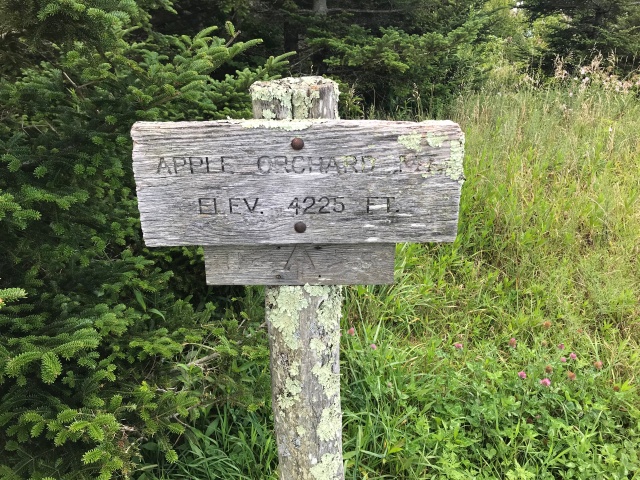
Apple Orchard Mountain


Flat Top Mountain


SW20 and paddle


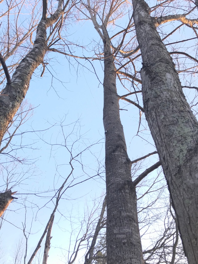
Dipole in the trees


What is SOTA?

As the name implies, it is putting a signal on the air from a mountain summit!  I think I’d heard mutterings of this hobby a few years ago, but it really first dawned on me after reading the June 2019 CQ magazine article, “Finding my true north”, by Mark Schreiner, NK8Q. I was so impressed with the article and interested in pursing this that I emailed Mark and we had some conversations. A really good intro video link he passed along to me is well worth watching if you want to know more. A full description of SOTA can also be found on its website. It was started around 2002 in the UK. Basically, it’s a worldwide database of summits that hams will hike or drive to, set up their equipment, and operate. There is a webpage to both”activate” summits (meaning they set up their radios from the summit), and to “spot” others who are currently transmitting from summits. There are points to earn for each summit you operate from. There are then awards you can achieve for given point totals. There’s a “mountain goat” award for those who earn 1000 points by activating and operating from summits and there is a “sloth” award for those who operate from home, contacting the activators on the summits! Lots to do and lots of fun.

I’m very new to SOTA, but I’m not new to hiking with my radios to hilltops. Back in 2000-2001, just before the dawn of the SOTA project, I was hiking up to a small hilltop in Tucson, AZ with my newly-built SW-20 transceiver! I used that very same blue table, the SW-20 is that green radio shown, and I have had that old straight key on a piece of wood since I was a teenager. It’s a trip down memory lane for me to do this project and the memories are quite fond ones.

How to get started?

As with any aspect of ham radio, or really any hobby for that matter, you can go as deep into it or as shallow as you want. There are many new specialized radios for this, there are special batteries and various accessories. Some of the key parameters as I see it are whether you are fit enough or able to do much hiking or not; the weight of the equipment you may need to haul; whether to become competitive with it or to do it in a casual manner; how much money do you want to spend (which is true of all hobbies!).

Cost of entry into this can be incredibly cheap. You can pick up small QRP rigs such as the SW-20, but with many more features now. There are do-it-yourself kits for about $40 up to over $200 for more sophisticated multi-band lightweight rigs. Pacific Antenna is in my opinion a great little shop for many of these rigs and accessories, but there are many others (I am definitely not the guru on all that is out there!). You don’t necessarily need to hike either, there are mountain tops with roads to the top. You don’t have to have fancy backpacking gear — I happen to own an old backpacker’s pack with external frame and I’ve pressed that into service. But a lot of this stuff you could put into a waist pack.

If you’re clever of course you can build a lot of your own gear. I built my own “link” dipole before I knew it was called that! It’s a multiband dipole where you select which band you’re on by use of jumpers. Tune it up in your backyard before heading out and you’re good to go. Also shown in those pics at the top is my “Super Antenna”, a cheap little vertical multiband antenna that’s lightweight and easy to throw together.

Dust off those radios!

SOTA gives me incentive to put some of my old QRP radios on the air. Sure I can do so at home but honestly I’d much rather spend my man-cave time with my TS-2000 and my desktop computer running digital modes. Or, spend time at my bench testing a circuit or building something. One of the main reasons I built these kit rigs to begin with was because of the coolness factor of taking them up to a mountain top and working DX. Or, at least as much DX as 1-2 watts can muster.

In 2000, I only had the SW-20. I loved (and still love!) that little rig and it has served me well. But now I have a few more kits from years gone by that, sadly, have not had much air time: the SW-40, Rockmite 40, and my poor SSB rig the Bitx20 (I made maybe 1-2 QSOs on that rig! I am just not much of an SSB operator). SOTA gives me some motivation to dust off these rigs and press them into service, and create some fun memories along the way.

By posting an activation alert online before your adventure, various SOTA participants around the world know to listen for you. When you get on the air with your wire and 2 watts, you can generate small pile-ups of stations trying to reach you! That is a lot of fun all by itself. You get the experience that a DX station might experience.

Unique thrill

There are many other cool things about this. Just the experience of connecting to someone hundreds or thousands of miles away with just a few watts is unbelievable! Yes we all have cellphones and internet wifi, etc, but this is using no network, no satellites, no cell towers — just a wire, a battery, and a radio I built myself out of a relatively small number of parts! I can service and repair these radios if they develop a problem. I can add features to the radios as time moves on! And the pride of crossing thousands of miles with YOUR creation is hard to beat.

One of the most amazing things with SOTA is the “SOTA-to-SOTA” QSOs. I just had my first of these yesterday — a ham operating portable in Canada, W0CCA/VE3 from “Mt. McKay” in Ontario! This is a distance of 1,400 miles. I do not know what power he was running, but likely QRP. I was doing my 2 watts from the link dipole.

After having only done 3 peaks so far, I’ve already had several QRP-to-QRP QSOs as well. These are not all other SOTA stations but just people running QRP around the popular QRP watering holes.

Final thoughts

I’ve always enjoyed the outdoors and hiking and bringing a radio along for the ride is a natural fit. Recent years have seen me take up running as a huge fitness challenge and because of this I really didn’t have much room for hiking (after running 10 miles or more, I really was not interested in hauling a heavy pack up a hill!). But I have been missing the outdoors. And where I live (Appalachian Mountains of Virginia) there are plentiful trails and small mountains/hills to experience (I’m from the west, where mountains are usually over 10,000 feet tall!). With the weather cooling off, fall can offer a great season to get out and explore, especially with leaf colors. I may not make “mountain goat” real soon but I do plan on tackling many more summits! Watch for me on CW, on 20 and 40m bands mostly for now.


Posted in Camping, SOTA, SW-40 | Tagged , , , , | Leave a comment

Outboard BFO to add SSB capability to AM radios

Circuit from “A Tunable BFO for Collins Filters” by Doug DeMaw, W1FB, January 1997 CQ Magazine

YouTube video of this project in action!

Sometimes projects come along that you are not planning for. This fun little BFO project was inspired through a series of events starting with the YouTube channel run by Gilles Letourneau (called “The Official SWL channel“). I have been a fan of this channel since discovering it about 2 months ago. Gilles has a great many reviews of shortwave radios and a weekly live stream with chat and many participants.

Some background

After watching the channel I was intrigued by some of the very inexpensive portable shortwave receivers on the market these days. The last shortwave portable I bought was the amazing Eton E1/XM, a true Cadillac of portables that rivals the performance of my Kenwood TS-2000 and Yaesu FT-857D ham rigs. It is a pleasure to listen to at night by the bedside, with a rich, base-filled sound and many helpful tuning features. These days there seems to be a flood of under-$50 radios coming from China. Among these discussed on Gille’s channel was a Tecsun R9012. It sells for slightly over $20 on Amazon at this time and is an “analog” radio (does not use DSP, no PLL and no digital display). Normally I would never consider buying a radio like this, but watching the videos I was surprised by the amount of stations being received and by the relative sensitivity of the radio. Because it was so cheap, I decided to buy one and play a bit with it myself.

This tiny radio (almost pocket-sized) will receive AM broadcast through shortwave and also FM broadcast. Unusually fun to operate and very inexpensive.

I was thinking, wouldn’t it be nice if this radio had SSB? I could then use it as a station monitor for my ham activities. Also it is so portable that I could take it to the field. There are slightly more expensive SSB portables now that also perform quite well (in fact, I also just purchased the XHDATA D808 for about $85 off E-bay, and it does a superb job on SSB). I then remembered from an old ham radio podcast I used to listen to called Soldersmoke that hams would take a 455 kHz BFO and add these to their old AM sets that were lacking SSB capability. I’m sure you can buy pre-made BFOs or scrap one out of a defunct radio in a junkbox. But I saw this as an opportunity for a new project and something fun to build and test.

Before even contemplating what circuit to use, I took my benchtop signal generator and just injected an RF signal into the R9012 to see if this would also serve the purpose of a BFO and “beat” against the incoming SSB signals. I tried the 40m and 80m bands where there are strong local ham radio signals. And yes! It worked and worked great! Suddenly this lowly $20 radio had SSB (and a nice digital display, although courtesy of the sig gen).

I then turned my attention to building a BFO. The idea would be to inject a signal at the IF frequency of this simple radio (and hopefully a few other radios I own). Doing a quick Google I learned that this radio used 455 kHz as its BFO frequency. Other radios I own such as the old Radio Shack Realistic DX-100 and my wonderful (but showing its age now) Sony ICF-2010 (whose SSB no longer reliably works) also use this IF. So with one circuit I could create a very interesting and more useful radio out of this $20 portable, I could resurrect SSB functionality in my old beloved Sony, and I could possibly improve upon SSB reception with the elderly DX-100 (it has a functioning BFO, but this BFO has never worked well even when the radio was new). The search for a circuit was on.

Doug DeMaw Collins BFO Circuit

I knew I needed an oscillator and the first thing I wanted to do was find a 455 kHz crystal and build an oscillator around that. I immediately ran into the problem that these crystals seem to be “unobtanium” these days (from reading various articles online, it seems that they have always been pricey). There were alternative circuits I saw on the internet using IF cans from old AM radios as the inductor in an LC oscillator circuit. The first one I tried did not oscillate. It was very simple however and I’m not sure it was well designed. Oscillator circuits in my experience can be very touchy and if your device selections and choice of component values are too far off, it will not oscillate. So rather than bang my head against the wall trying to re-invent an oscillator, I searched for kits I could build. The first place I go for things like this tends to be FAR circuits . Sure enough, I quickly found the DeMaw circuit from the late 1990s, published in CQ. The website does not describe the circuit or show the article, it only supplies a pre-made circuit board that you can order and stuff yourself. But it gives information on where to find the article. I found an archive website for CQ magazine articles, purchased a copy of the DeMaw article, and was intrigued. It looked like exactly what I wanted for this project!

When I see the name DeMaw I also know from experience that this will be a nice project. The late ham operator wrote many wonderful construction articles for QRP radio projects and co-authored “Solid State Design for the Radio Amateur” which likely inspired the later publication “Experimental Methods in RF Design”. I also have his “W1FB’s Design Notebook” on my shelf. He writes in a clear manner and the circuits work. I was happy to put this little oscillator together.

The circuit cost me about $25 all told. This includes about $9 for the board (with shipping) from FAR circuits. The other components I needed were the 1800 and 2200 pF capacitors in the Colpitts oscillator, the varactor diode and the 25k pot. The rest of these parts I had in my junkbox, including others I added to the circuit that are not shown in the diagram. The bigger your junkbox obviously the cheaper the project! I have been collecting various parts for about 25 years now, so it sure helps.

The two IF transformers may be harder to obtain for some people. They used to be dirt cheap apparently but these days are about a dollar apiece at Mouser.com (look for part # 42IF103-RC, made by Xicon). I also got my capacitors, varactor and the variable resistor pot there. You can also get all the other parts there such as the zener diode (I just happened to have this in my parts supplies). Resistors and capacitors are things I normally have on hand because I build many kits and projects for radios. I even had some of the NP0 capacitors specified (which are more stable with temperature, great for VFOs).

Implementation and use

It’s important to use the proper IF can for this oscillator to work properly. Originally I had used another one out of my junkbox and the inductance was too low. The oscillator put out some random junk signals and would not really oscillate. Once the proper values are installed in this circuit, it runs great.

The author quotes 20V P-P output at 455 kHz with a 390 ohm terminating resistor. I obtained a bit more voltage than this on mine. The amplifier stage helps to deliver this robust signal. My hope was that I could simply inject this signal into the telescoping antennas of my portable radios and not have to perform surgery and inject the signal directly into an IF stage somewhere (not only would this be more cumbersome but since I would like to use this on multiple radios it would no longer be portable). As luck would have it, the circuit works great with my radios in this regard. I can push this 455 kHz past any filtering stages and into the IF stages of my radios by simply clipping a lead wire to the telescoping antenna inputs. The circuit is also very very stable once a suitable warm-up period has elapsed (maybe 5-10 minutes or so).  As I write this article, it has been running on my ICF-2010 listening to a net on 20m SSB, and for the past hour I have not had to re-tune once!). It goes to show that “good old” analog circuits aren’t all drifty poor quality experiences.

The variable pot serves as the BFO knob and is used to tune in both USB and LSB signals. The IF can in the Colpitts oscillator circuit is a more coarse adjustment and is used to help center the BFO signal within the radio’s IF passband. Once this IF transformer is adjusted for a particular radio, you really don’t need to touch it again (and with my radios, they were all fairly close with their IF passbands and this can did not really need to be re-adjusted). The IF can in the amplifier stage is adjusted for maximum output power. More power can be obtained off the collector of Q2 than from the output of this transformer. I may still experiment with this; for now, I’m taking the output from the transformer.

Depending on the radio, the BFO level can be too high or too low. I decided that I would need another pot to vary the output level of this circuit (I did not want to have to use a screwdriver to play with the T1 can! A simple knob from a pot would be much easier). I found that a 10K pot worked ok for this purpose and I have many in my junkbox. With the R9012 I find I have to dial down the output to minimum levels (using all 10k-ohm) or it can mute out signals. With the ICF-2010 I can usually run it full blast.

I also installed a power switch and 12 V banana plug ports for power input. That is a drawback of this design, it relies on 12V. I have a benchtop supply for 12V but for field use it would be nicer to have it run off of a 9V or less battery. Since I probably won’t use it in this manner, I will not investigate a modification. However, for a 9V battery it would probably only require running the circuit at ~6-7V, using a different zener and adjusting transistor bias resistors slightly. The circuit requires very little current to run, about 15 mA. With my ancient Radio Shack rechargeable NiMH 9V batteries, 150 mAh, they would last 10 hours on this circuit (I’m sure more modern batteries would do much better).

I also run a ground lead along with the signal lead from the BFO box to the radio of interest (speaker wire, with the two wires attached together like a balanced feedline). A better way might be to use a coaxial cable to run this signal, but my lead lengths are short and I seem to be able to get away with this. At the end are banana plugs I soldered to the wires, one attaching to a ground port of the radio and another to the whip antenna or antenna port if one exists.

Finally, I had to put all these ideas and mods into a box. I found a “Juicy Fruit” metal box I’d been saving for something like this! Along the lines of “Altoids tin” projects, I tend to save interesting metal boxes for RF projects. You can’t beat the price, and you get a colorful paint job and logo along for the ride!

Red lead goes to telescoping antenna, black lead to ground connection of incoming antenna cable.

Concluding thoughts

There are other methods to achieve oscillation at 455 kHz that likely use timer ICs or digital technologies. This is a simple, low-part count circuit that works well and I’m very happy with it. In fact, it performs much better than I had anticipated. It has allowed me to continue to use my ICF-2010 on SSB when that functionality had died several years ago (attempts to repair this failed! I may not have the necessary skills). And for far less than the price of a new SSB portable, it gives that functionality to lesser radios lacking SSB entirely (or in the case of the Realistic DX-100, radios that have SSB but a rather hard to use BFO).

Using it takes some getting used to however. For one, you are listening to double sideband with this configuration, so you have to tune past the unwanted sideband to the one you want. If your radio has a narrow filter, this helps a lot to eliminate resulting QRM. Also, stronger SSB signals overload a bit and can be too strong for the injected BFO, so you get a loud and distorted Donald Duck sounding voice. You have to implement RF gain in some way to knock down these very strong SSB signals, whether that means decoupling somewhat from a longwire antenna or in some way de-tuning the input RF signal (I put an antenna tuner in line and de-tuned it for the loud signals, but an outboard RF gain attenuator box would be quite useful to have for some of these cheaper shortwave portables anyway, and this may be another quick project in my future).

In general though I found this to be a lot of fun. I was amazed to see what more the R9012 could do! As a bonus, I attached a ground lead for the R9012 from it’s negative battery terminal and used this to connect it more properly to my tuned longwire antenna (and my BFO box), and this improved performance of the R9012 dramatically. At times it seems to rival my ICF-2010 for sensitivity, which is astonishing. It suffers from images and its tuning is quite challenging (it really needs fine tuning!), but for a $20 radio I’m over the moon.

Posted in Uncategorized | 1 Comment

Back to the blog! Hamming with dipoles in trees

It’s been a long dry spell away from the blog. Time to re-connect!

In the past two years I’ve started a new job/career and began a house building project. Lots going on. I’ve also become an avid astrophotographer, and that hobby has consumed most of my free time of late.

The electronics bug never left though and it’s starting to rekindle. I had attempted to build another VLF converter type project for a special crowd-sourced research project associated with the solar eclipse two years ago. That project flopped. There was a loop antenna, a circuit and an app on the smartphone. The app never quite worked right with the circuit and after fighting with it off and on for over a year I finally gave up and just took the chips out of the board, tossed the board in the trash and cleared off my benchtop! It felt very cathartic.

The new property where we’re moving to (and building a house on) has lots of land for an antenna farm and in one corner there are some trees. I’ve strung up a 40m and a 20m dipole already. I’m amazed at how much better the simple dipoles perform over my end-fed long wire system I’m using at the QTH now.

If you look real close you can see a balun way up that tree

One of my first contacts on the new 40m dipole was Australia! I have never worked a VK6 on 40m, at least not in the last 20 years and never from Virginia. I heard him working someone, looked up his callsign on QRZ and sent him an email. He suggested trying a sked. So at about 7 pm local time (2300z) we made the connection down on 7002 kHz. Amazing! He was not that stunned. I guess he regularly works the US during the greyline of his sunrise.

Dusting off the workbench after I cleared away the debris from the failed VLF eclipse project, I unearthed a multi-band arduino-based rig kit. And now I see that Farhan has a new multi-band Bitx rig which is worthy of consideration. I feel very rusty though. Looking over my past projects I feel like I don’t remember much about how they even operate now.  But it should come back to me.

I’ve also been compelled by shortwave listening again. I am surprised to find a number of broadcasters who are still sticking with it. My impression was that they had all folded up about 20 years ago. It has been fun browsing some shortwave scheduling websites and tuning in on my Eton X1 (the best portable I’ve ever owned, just slightly better than the old ICF-2010, which incidentally needs a stint on the workbench to troubleshoot). There’s still something fun about tuning around the bands. Many of us got our start as shortwave listeners long before getting into ham radio.

If you’re looking for an entertaining short wave enthusiast, check out the following YouTube channel: https://www.youtube.com/user/OfficialSWLchannel/  The guy who runs it lives in Quebec, Canada. He has live chat videos each week which run several hours and there’s great conversation about radios. He tunes in to stations during the live chat on his SDR (with giant monitor often in the background) or using one of many portables he owns.

When I decide on my next endeavor(s) I will start posting some updates to the blog. I don’t know if I still have any followers at this point! If you stumble across this though, welcome aboard.


Posted in Uncategorized | Leave a comment

LF converter, tuner and antenna

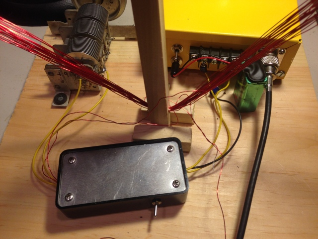
Completed loop antenna, yellow converter box and tuner box

Completed loop antenna, yellow converter box and tuner box

A few years ago at Dayton I was visiting the FAR Circuits tent and ran across a little circuit by Larry Coyle, K1QW, for converting the LF and VLF band to 4 MHz. This was done to allow users to experience the perceived improvement in sensitivity of many receivers in the 4 MHz band as compared to the often poor performance down in the LF band. A very well-written two part article accompanied this circuit and can be found in the November 2008 QST, “A Modular Receiver for Exploring the LF/VLF Bands”. Part one covered the circuit I put together, the converter. Part 2, which I will probably not explore (at least not anytime soon) was a software defined receiver. It is described as a good way to get introduced to software defined radio and might be worthy of consideration.

Converter Circuit

The converter is another SA602-based creation, incorporating a switchable 12 dB attenuator to knock down out-of-band signals which may overload the mixer chip, and a “5-pole elliptic low-pass filter with a cutoff around 550 kHz” (to reject MW broadcast band signals). The parts to build most of this came out of my junkbox and are commonly available. I did have to order the transistor he used for the local oscillator input into the mixer, the 4 MHz crystal, a TL317CLP voltage regulator and the Schottky diode used in the power supply.

I was going to post the circuit but I will refrain as I do not see it in the public domain.

The basic functionality of the circuit is straightforward. The signal from the antenna is low-pass filtered and up-converted to 4 MHz. A transformer off the 602 chip converts impedance to around 50 ohms for export to an external receiver.

The description of this circuit implied that the full spectrum from DC up to about 500 kHz should be received fairly well with a loop antenna and no tuning should be required. However, this was not the experience I had with this circuit.

Antenna for LF

Originally I wound a ferrite rod style antenna, with an inductance of about 1 mH. This was deaf as a fencepost and I could not receive any signals whatsoever either using the converter box or via direct input (mismatch and all) into my Kenwood. I injected signals into the converter box from my signal generator just to verify the circuit was working, and sure enough I was getting output in the 4 MHz band. But no beacons and not even any AM broadcasts were coming through at the low-end of the MW band.

Reluctantly, I wound a larger loop antenna on a wood frame, the wire forming a square of about 2 feet on a side. I had one of these as a teenager and had kept it for a few years but I found traveling with it to be cumbersome and tore it down. This time around I built it to be easily taken apart and re-constructed at some later time. Or at least that was the plan.

Normally these antennas are constructed such that you make some grooves at the ends of the support beams and wind the coil around the frame to sit within those grooves. But I wanted the wires to be contained better than that, and thought I’d instead drill holes at the ends of each beam and just thread the wire through the holes.  Bad move! It took HOURS to wind the loop this way! And there really is no simple method to thread these holes with large lengths of wire. I ended up doing 20 painstaking turns in this manner, yielding about 700 uH.

The pain of winding yielded results though: signals! I could receive some NDB beacons in my local area (two total). And at least the local broadcasters could be heard.

But signals were VERY weak. I found that the beacon was almost impossible to hear, and I could actually hear it stronger off of my end fed longwire tuned to 40m on my TS-2000. Something seemed way off to me.

It could be that because my loop was a little smaller than the author’s the impedance was too mismatched (his was 30 inches on a side to my 24 inches). But the entire band was really dead. I did not hear any lightning “whistlers” even as the Virginia summer thunderstorm season was raging on around me. That was kind of a disappointment.

Tuning the loop

I decided to do a little engineering on the circuit and investigate the impedance. I put the antenna on my TAPR VNA and soon learned that the impedance was very high and inductive. Not surprising I suppose for a big coil. The input impedance of the SA602 chip is also rather high, around 1.5 kohms. So it might not be that badly matched, but for such high impedances my VNA tool is a little hard to interpret (the values seem to swim all over the Smith chart). I’m not really sure if I’m seeing a kohm or 100 kohms.

I wanted to see if I could bring the impedance down closer to 50 ohms at around 200 kHz and just feed my Kenwood with it directly, without the converter, and see if I could at least make out the beacon. In order to do this in a practical manner I needed to use a balun, then tune the hot side with a series capacitance (using the balun means I don’t need to try to simultaneously tune two lines). This actually worked very well! I have a really nice air variable in my junkbox that will tune from a few pF up to about 1200 pF, and I pressed that into service. I found someone else on the internet (see his interesting little writeup at lf loops) who had posted a design for their loop antenna and said that they found a good match by using 2200 pF capacitors in series just before the balun. Having difficulty initially finding a match, I decided to copy his layout and amazingly I got very good matches from about 200 kHz up to 600 kHz! Wow. I felt like I struck gold.

Plugging this into the Kenwood, signals began coming in much better. The level of the beacon (at around 270 kHz) was stronger now than off of un-tuned wire antennas and the local broadcasters were booming in. Progress.

But I still wanted to make use of my converter box! After all, I had built the circuit into a nice metal box with connectors, switches and even a nice little green LED! I even painted the box yellow to signify VLF lightning signals.

Since I knew how to tune this to 50 ohms I decided the easiest thing to do would be to just bump the impedance back up to some arbitrary high value to match what the converter box would be expecting. Admittedly by this time I was losing interest in the project and kind of wanted to wrap it up, so making this match perfect was less important to me than just getting it to work reasonably well.

I ended up rolling two more toroidal transformers, one a 1:4 balun (to bump up impedance and convert back to a balanced transmission line) and one a simple 1:2 transformer. With the two transformations I should get an output impedance of about 800 ohms. I also found that if I switched in another capacitor in parallel with my big variable I could get it to tune down to about 170 kHz. The details and a picture are shown below.

IMG_0028

Notes on the tuner circuit for the loop and loop construction

IMG_0017

Innards of tuner box (manhattan construction on some copper clad)

IMG_0025

Large air variable, yellow converter box and small black and silver tuner box sitting on a wood plank at the base of the loop antenna

Performance

The completed system worked very well. Signals and even just the basic noise floor are elevated up to reasonable levels throughout the LF band and a big improvement from the tuned loop by itself. It seems that my Kenwood’s sensitivity in the 4 MHz band is indeed superior to its LF performance. Below 170 kHz though performance rapidly deteriorates and the system is pretty deaf. I could not find values of capacitance or inductance to match down below 170 kHz, although I’m sure such a system could be constructed. Increasing the difficulty is the fact that my VNA does not tune below 200 kHz so I would need to use other methods to design a match.

On the first night after finishing this system I actually heard a broadcast station from Cuba on 570 kHz! It was “Radio Reloj” (https://en.wikipedia.org/wiki/Radio_Reloj) I was surprised to say the least. Apparently when some other stations on the frequency are off-air it is common to hear this Cuban clock station up and down the east coast of the US.

The rest of the LF band was pretty disappointing. I did pick up one more NDB beacon. But there were no pirates or experimental stations heard. And no lightning whistlers! I’ve since learned that there are other design strategies for listening to lightning, employing audio amplifiers. I will either try one of those or contact the author of this article for his thoughts.

I believe I will eventually play with some of the audio-amp style lightning circuits. And I’m also a little curious if anyone else is hearing the megawatt station NAA in Maine that is communicating with submarines in the VLF region (below 100 kHz somewhere). I couldn’t hear NAA, WWVB or the LORAN system at all. So, while I always enjoy tuning things and making baluns and seeing them work, it would also be nice to hear interesting signals!

I’m running out of time before my schedule kills most of my ham radio play time once again. But I’m hoping to look at some Arduino stuff and a Raspberry Pi I picked up at Dayton. Stay tuned and happy soldering.


Posted in antenna construction, LF, lowfer, VLF | 1 Comment

SW-40 completed and on the air!

My completed rig on lower right, inside my pickup truck at the Grindstone Campground in SW Virginia

My completed rig on lower right, inside my pickup truck at the Grindstone Campground in SW Virginia

It’s a great feeling.

My thus far relatively modest journey into homebrewing had another high water point as I finally completed this QRP transceiver, and even better, made my first QSO with it out camping in the woods! The antenna was also homebrew, my multi-band jumper dipole for 10-20 m. The antenna was also used heavily with my commercial Yaesu 857D rig (barely seen on the wooden mount, upper-left). No, I’m not strictly homebrew, I do sometimes like to get on the air with all the bells and whistles of the pro-rigs. But the most joy I had, by far, was the one contact I had on 40 with the SW-40 (I wasn’t actually on the band very long, and had to use a hamstick whip antenna, or else I’m sure I would have made more QSOs).

Balun of multiband homebrew jumper dipole suspended in the trees

Balun of multiband homebrew jumper dipole suspended in the trees

The antenna was created following a much less successful attempt at camping with dipoles last year. The wires were ripping from SO-239 connectors and were very rag tag and falling apart. I knew I could do better.

The finishing touches on the rig came together nicely. I managed to find one of the old, large 1/4″ mono headset jacks from a junkbox given to me by my elmer many years back, and I used that for the key connection (my straight key uses one of these and it’s just kind of a tradition with my rigs, if space allows). You can see it at right (with a key plugged in). It put a nice touch to the creation to have something in there from fellow hams from the past.

Backside of rig

Backside of rig

I also like to put SO-239’s on my rigs. I know lots of people are using BNCs or other smaller connectors, but I like going “old school” and it mates with everything in my shack. I also like having two choices for power hookup on my rigs: the banana plugs and a power socket from Radio Shack (I believe it’s called a “type M”). I suppose I should make up my mind and stick with one choice! But I’ve found it convenient for the power hookups I typically use.

Front side with Bencher and an old "Curtis K5" keyer!

Front side with Bencher and an old “Curtis K5” keyer!

The box, in case anyone was wondering, was purchased from “QRP kits” in 2015. It was designed to be used with their version of Farhan’s BITX rigs, but I really liked it and wanted to use it for different kits too. I am not particularly skilled with metal working, nor do I have access to any specialized equipment. So having a nice box pre-made is a real treat.

The lettering is just your basic transfer lettering I’ve used since I was a teenager. It can be found at art supply stores or online. It isn’t the best way to go but I haven’t yet worked out how to do the laserjet printer transfers. I then spray some clear coat on top to keep the letters on.

This cabinet has pre-drilled holes for a speaker. I don’t currently have a speaker installed and I’d need another audio amplification stage to power one. I may add this down the road or I may not. It would drain a little more current and most of the time I prefer headphones on CW anyway.

The display was also purchased from QRP kits and itself was another kit, the KD1JV digital display. One note about this kit: it radiates some noise on 4 MHz, which is the IF used in this kit. I spent a day just tracking down the source of this “birdie” and it was driving me mad. I finally realized it was the display. Shielding helps to knock it down, but given the constraints of a pre-made PC board from the kit, it is hard to find real estate to solder a shielded box around anything. So I did a workaround of installing a power switch to the display. Once I’m tuned to a known frequency, the display goes off. It also conserves battery power which is nice when running on AAs out at a campsite.

I dug up my OLD Curtis K5 “Lil Bugger” keyer from my childhood and used it with the SW-40. It worked great! I always liked the thumbwheel to dial up what speed you want on CW, and the push button on the back to key up for tuning. I am sure more sophisticated and smaller keyers can now be installed inside the box, but this brought back fond memories of late nights on the air with an old Galaxy III and a dipole on my roof.

My one QSO was with W8IX who has the appropriate nickname “Dit”. He lives in Indiana and is a more serious homebrewer. So it seemed like it was homebrew-to-homebrew operating! Couldn’t have asked for a more fun 1st QSO with this rig, which has taken about 14 years to finally complete!

IMG_1932

The unboxed board and display

I’m now moving on to other things. I’ve got a VLF converter board that I picked up at FAR circuits at Dayton a few years ago. I’d actually already ordered most of the parts for this, and the rest I had in my junkbox. I should wrap this up later in the coming week, if all goes well, and I hope to be hearing some interesting noises from lightning down around 5 kHz! The LF and VLF bands are pretty unexplored regions for me, so this is breaking some new ground. And I’ve never built a converter type project before (translating VLF up to 4 MHz). I guess unfortunately it’s another NE602-type project (these are truly everywhere), so I won’t be breaking new learning ground really. But it should be fun and I’ll be posting about that once it’s done.

Posted in antenna construction, Camping, first light, first QSO, KD1JV digital display, SW-40 | Leave a comment

I’m Baaack! Dusting off the station. And, the SW-40 is on the air!

Completed SW-40 kit board from Dave Benson K1SWL

Completed SW-40 kit board from Dave Benson K1SWL

I am back to the blog after an almost 1 year hiatus from all forms of ham radio! It’s good to be melting solder once more. Really, really good!

During my down time, I have seen hits to my blog every so often. Someone seems to find my blog and read several entries, maybe looking for some clues in whatever project they’re working on currently, or just to satisfy their curiosity, boredom, or whatever. I’m glad it seems to still be useful or interesting to some out there. Because I don’t post anymore, I’ve lost any kind of regular following, which is understandable. Still, I’ll pass this blog entry along to Bill Meara of SolderSmoke in case some of his friends might enjoy the entry.

I had stuffed the kit board for the SW-40 last August but I was missing the PA transistor, a 2SC2078. I think I had stolen one from this kit to replace one I’d managed to blow up in the SW-20 some years ago. No worries. Some web browsing had found a supplier and the part (and some spares) arrived about a week later in the mail (I had none in my junkbox and due to the low cost I wanted to just use the intended part rather than make a substitution).

Unfortunately, my time was extraordinarily limited in both the fall and spring. I had ZERO time to play on radio. All that time, the kit, and my radio hobby life, sat idly by on the bench, untouched. I would occasionally look across the room at it, longingly, remembering happier days when I could play radio! It was sad to be honest. But I knew eventually I would find an opening again to play. And, come May 2016, I finally did.

When the dust settled in my schedule, the first order of business for me was to do some late spring antenna work (an SW-40 without an antenna is not too useful). I think many of us play antennas during the warm months of the year (at least those of us who live in colder latitudes).

I found that some severe windstorms had spun my 17 m dipole around on its mast, and it was beginning to torque the coax feed. The U-bolts normally hold quite well but I’m using a cheap plywood mast-to-dipole plate, and after a year some slack had developed, allowing the dipole to rotate a bit. This was solved by running a pair of bolts through the plate and mast. If any rotation takes place now, it will happen at the base of the mast, which can be easily corrected.

The longwire/tuner arrangement I use for most of the HF bands had held up perfectly. The homebrew tuner (see earlier blog entries for that!) is protected from the elements by a Rubbermaid “Roughneck” plastic tub, and it has done its job. The longwire had sagged slightly, which was easily corrected. I set the controls for 40 m CW and had under 1.5:1 VSWR, just like a year ago.

Feeling the ham radio mojo starting to return after the antenna work, I finally came back to my workbench.

This is no simple thing. Having been away for so long, it took me some time to remember what was what. I felt like I’d been in suspended animation and was just coming to.

Even approaching the work area after such a long time away seemed like some type of religious experience to me. As I rediscovered where things were again, the excitement began to build. I really wanted to finish this little rig and get it on the air.

The long-dry yellow sponge of the soldering station once again found water. The iron was switched on. The Kenwood TS-2000 behind me was turned on to listen to the background banter of hams on 40m. I was back in business.

I soldered in the PA transistor, found some pots for volume control and tuning in my junkbox, and soldered up some leads for a key. I did the “smoke test”, applying the 12V DC. And…

Nothing!

No smoke, but no signal anywhere on the 40m band. I double checked my cabling and my monitor rig and tried again. Still nothing.

The current draw was very low and barely changed from RX to TX, which is a very bad sign! It was at this point that I felt some frustration creep in about the manner in which the kit was built and NOT tested, stage by stage, which is what I normally try to do. Because of limited time last summer, I had simply thrown all the parts into the board and crossed my fingers. Let this be a lesson to those novice builders out there! This is NOT the way to go!

Fortunately, I guess, this (and probably most of my near-future radio projects) are simple enough and I’m familiar enough with the circuits that troubleshooting is not that hard. In fact, having it NOT work right away provided a mystery. And forced me to go back, stage by stage, to investigate my creation. Which was what I should have done before anyway.

The scope, which I’d not touched in a year, was activated. Dave’s kit has excellent documentation which actually has almost all nodes of the circuit annotated with both the DC and AC expected signal levels! This almost seems like cheating to me! But hey, it’s there and I used it.

I went back to the LO. No troubles there, a very solid signal around 3 MHz from the Colpitts. Then I checked out the 4 MHz oscillator of the NE602 chip of the TX mixer. Again, solid 4 MHz signal and the voltages checked out. EXCEPT — it died before it reached the input of the following buffer stage and “Q4”.

There are two IF cans, T2 and T3, between the TX mixer and the following buffer stage. The signal was fine on the primary side of T2, but something happened to it by the time it hit the secondary of T3. It was around 500 mV p-p when a 1.5 V p-p was expected. I found out that the capacitor C32 in parallel with the secondary was not the right value. Somehow I’d put in a 150 pF instead of a 47 pF. The change must have resulted in more RF getting shunted to ground, and very little was left to apply to the base of Q4. Once swapped out, I was able to tune T2 and T3 and…voila! The SW-40 came to life!

I was able to get 2.5 W out of this rig, which is the upper range Dave cites as the expected output (1.5 – 2.5 W). That was very satisfying. And the signal is clean as a whistle on the scope.

I was thrilled that the RX side worked fine, first go. I recall that I HAD actually tested some of those stages as I was building the kit, so that probably helped me there. Signals poured in to the little rig immediately and at loud amplification. How thrilling! There is always something special about “first light” for a creation of your own, even a kit.

I feel that the troubleshooting aspect of getting the rig on the air helped to make this kit feel more personally connected to me. Had everything just worked after stuffing the parts, I think part of me would still have wanted to go back through with the scope and measure the various signals coming out of the stages. It seems way too appliance operator-like not to. And all of Dave’s annotations of expected voltage just beckon the hobbyist to play.

What comes next is the boxing of the rig. I know some builders don’t really put their creations in much of a box. But I do like to sometimes take the rigs out camping or picnicking somewhere, and having it in a contained enclosure really helps! I purchased a box and a nice digital tuner kit from QRPkits.com last year, it’s the same one being sold for their Bitx kits (and the one I used for my Bitx17 I built two years ago, the KD1JV digital dial). Another option for a tuning “display” which I had used with my SW20 about 16 years ago was a kind of ingenious kit sold by Dave that would announce your frequency by sending CW through your headphones. It took up very little space. But I kind of like glowing numerals.

So, this one should be a sharp-looking little rig once completed. And I fully expect to make many CW contacts with it. Heading towards another solar minimum, it’s nice to have this old kit completed for a lower HF band. I’ll post a blog once this is boxed.

That’s it! Nice to be back in the “brotherhood”, at least in some small way.


Posted in Uncategorized | 2 Comments

Crystal filter analysis, SW40

filter on board

Three crystal filter from the Small Wonder Labs 40 CW transceiver, connected to the TAPR VNA for analysis

I’ve been away from the blog for quite awhile, mainly because I ran into several roadblocks which stymied my progress with the SW40 build and analysis.

I really wanted to re-visit the type of analysis I did when I built the Bitx20A kit, but the laptop I was using for the TAPR VNA up and died on me!  I really had no time or interest in tearing apart that unit and trying to “fix” it, and it was a sluggish and rather cheap netbook style older machine anyway, so I ended up buying a new cheap laptop to replace it.

Well, unfortunately, that did not resolve matters.  It’s a long and boring story.  But the upshot is, the TAPR software will only run on computers running on a 32 bit OS, and the new laptop was running 64 bit Windows 8.1!  How frustrating!  I contacted the software developer for this tool but didn’t obtain a solution.  I ended up having to partition the hard drive of my desktop and installing a 32 bit version of Windows 7 on it!  That cost some dollars too, unfortunately.  But I’m happy to report that I can at least use this fun and educational VNA tool again, albeit from my desktop via a lengthy USB cable.

If anyone reading this is having similar trouble with the VNA, I am working with a tech rep from Cypress (the maker of the USB chip in the VNA) to see if they can create a 64 bit version of the driver (or help me find a workaround).  I’m not too optimistic.  But if they do, I will create another blog specific to the TAPR VNA and the driver solution, and will also pass along to the TAPR team and the designer.

Back to the SW40!

I revisited my blog from last year on analysis of crystal parameters.  Most of this information can be found by digging through books by people like Wes Hayward or some ARRL handbooks and other resources.  I went through that process last year, discovered the model for the crystals used in RF filters, and discovered the algebra and techniques necessary to find the values of the parameters of that model.  That previous blog has the gory details of that process and I won’t repeat it here.  I will pass along the results and some plots though.

Crystal parameters:
Rs = 5.5 ohms
QL=56223
QU=572220
Lm = 125 mH
Cm = 0.0127 pF
Cp = 4 pF
Series resonant frequency: 3.998944 MHz
Parallel resonant frequency: 4.006180 MHz

And a plot of the S21 for the crystal:

SW40 S21

These numbers, and the plot, compare fairly well to the ones obtained for the Bitx20A filter crystals.  The unloaded Q is higher in this crystal than it was for the other kit.  And the Cm was a little different.  But generally the numbers seem in line for published values typical for these crystals.

Next I built the filter on some clad and connected to the VNA.  The filter is meant for 4 MHz as you can probably tell by the plot.

SW40 crystal filter

SW40 filter tight zoom

The resolution of these snapshots is rather poor for some reason.  But the 3dB points are roughly 3.998922 and 3.999393 MHz for a bandwidth of 471 Hz.  The up and down wavyness in the passband is fairly dramatic and more than 6 dB down from peaks.  But I took the passband as being 3 dB down from these outermost peaks.  Beyond these two points the response drops off dramatically on either side.

The 6 dB bandwidth according to the specs in the assembly instructions from Dave Benson was 500 Hz, so this is spot on it looks like (which is more reassuring from the standpoint that my test setup is accurate than it is a validation of Dave’s work, at the moment at least).  This is much narrower than the Bitx20A filter, but that’s obviously by design — this is a CW rig and not an SSB rig.

This time around I was determined to use a pre-packaged filter analysis software instead of “Puff”.  Puff would work but it’s very basic and I thought it was high time to use some software meant for this purpose.  I tried the AADE package (V. 4.5) and after about an hour playing with it I was able to get a very nice S21-style plot out of the thing.  The general shape and the bandwidth lined up very closely to the output of the VNA, which was exciting.  The main discrepancy was the frequency of the passband was shifted about 4 kHz  downward, but I’m not sure I’m really that concerned for now.

Filter plot output from AADE

Filter plot output from AADE

I was very impressed that the shape of the passband was clearly repeated by the modelling tool, with that second dip being a little deeper and wider than the first.  I was also excited by the fact that it came up with a 3 dB bandwidth of 455 kHz, only 16 Hz different from measured!

I’m not sure if this is the best or most intuitive filter analysis software around.  I thought there was another package made by Wes Hayward or someone.  But given that I only needed about an hour to create a model and input my crystal parameters and generate a useful plot, I’d say that it did the job.

So I will continue on building this kit.  I wanted to refresh my mind about these formulas and the filter analysis generally, and at least I got to play with one of the software tools out there on the net.  I’m afraid I’m going to have to rapidly finish up the rest of this kit though with very little analysis, as I’ve run out of “play time” this summer and will very soon be inundated with studies and projects.  I hope to post a few more blogs on progress on that front.

Posted in crystal characterization, crystal filter, SW-40, TAPR VNA, Wes Hayward | Leave a comment